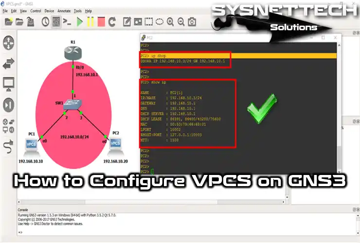
When designing network projects using GNS3, you can use VPCS instead of virtual machines for performance.
How to Install VPCS on GNS3
In the GNS3 program, there are network devices such as Switches, Routers, and Hubs in the Devices panel. You may need to add virtual machines to this program when you prepare for the Cisco exams.
On the other hand, we recommend that you use a Virtual PC Simulator (VPCS) since using a virtual machine will put an extra load on your computer.
Using VPCS is a more specific and faster method. You can also call VPCS a virtual computer simulator.
How to Use Virtual PC Simulator (VPCS)
To install VPCS on the GNS3 network simulator, follow the steps below.
Step 1
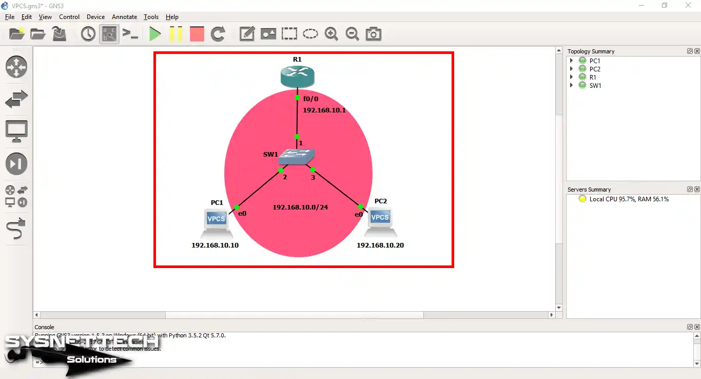
First, open the GNS3 simulator, create a topology as shown in the image below, and then add two Virtual PCs to the workspace.
Step 2
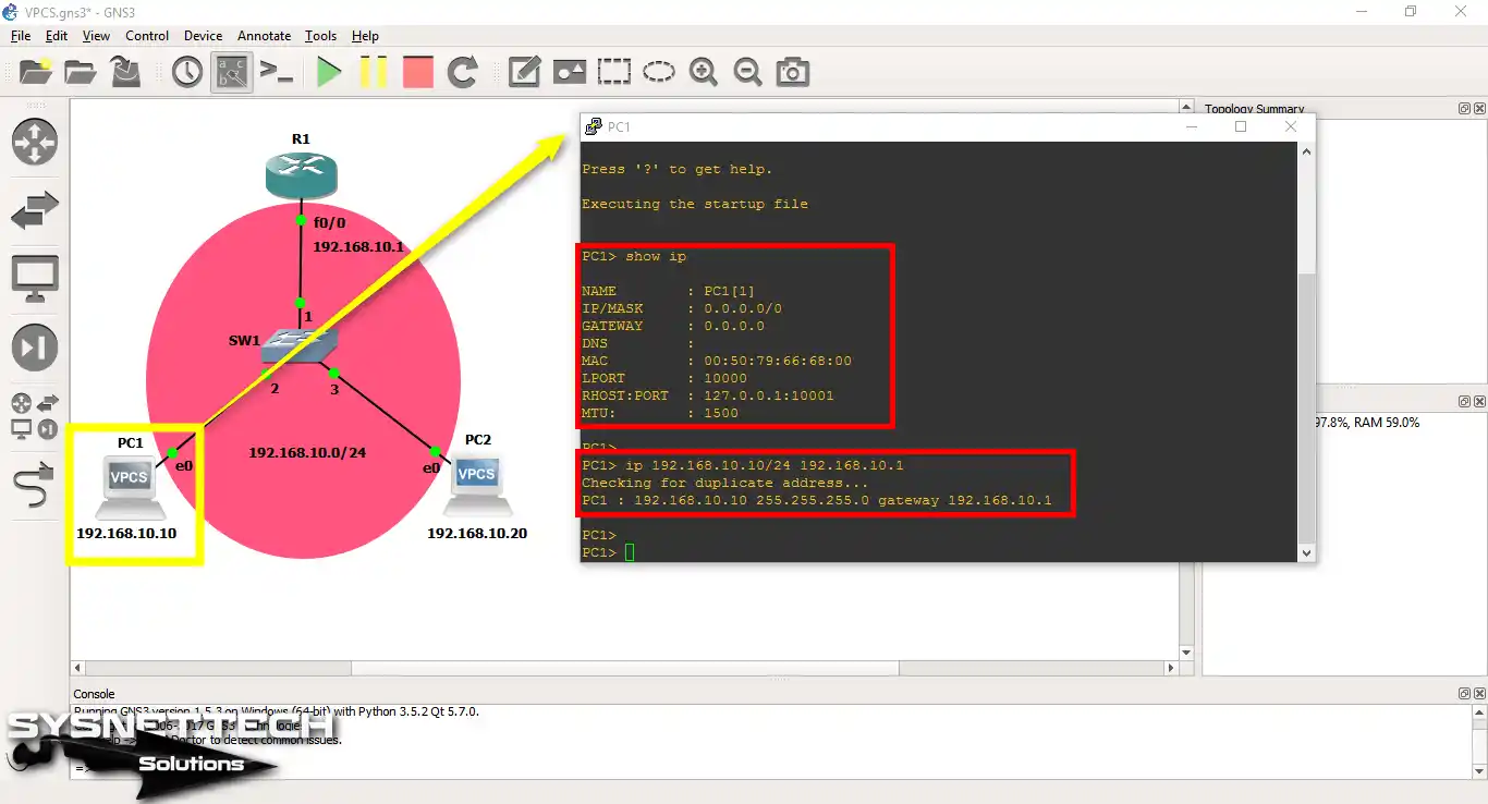
After opening the CLI prompt by double-clicking on the VPCS PC1, execute the ip (ip address) (subnet mask) (default gateway) command to configure its TCP/IP settings.
You can use the show ip command to check the TCP/IP settings.
PC1> show ip
NAME : PC1[1]
IP/MASK : 0.0.0.0/0
GATEWAY : 0.0.0.0
DNS :
MAC : 00:50:79:66:68:00
LPORT : 10000
RHOST:PORT : 127.0.0.1:10001
MTU: : 1500
PC1> ip 192.168.10.10/24 192.168.10.1
Checking for duplicate address...
PC1 : 192.168.10.10 255.255.255.0 gateway 192.168.10.1
Step 3
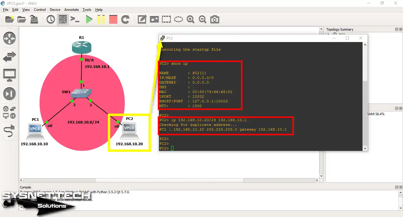
In the same way, the TCP/IP settings of the VPCS PC2 are configured.
Step 4
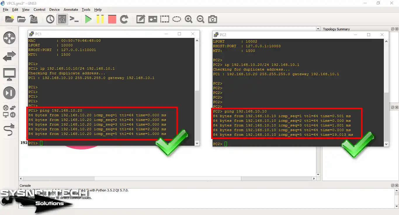
Ping will check the connection between PC1 and PC2.
Step 5
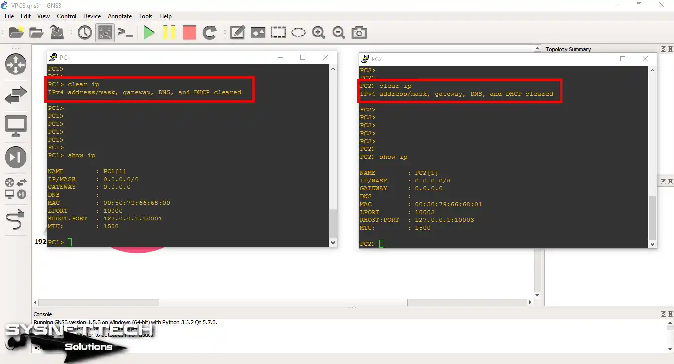
You can use the clear ip command to delete TCP/IP configurations.
Clear the settings on both PCs and then check the TCP/IP settings again using the show ip command.
Step 6
After assigning IP addresses to VPCSs, configure the Cisco Router as a DHCP server using the following commands.
R1#conf t
Enter configuration commands, one per line. End with CNTL/Z.
R1(config)#interface fastEthernet 0/0
R1(config-if)#ip address 192.168.10.1 255.255.255.0
R1(config-if)#no shutdown
R1(config-if)#exit
R1(config)#ip dhcp pool DHCPLANPOOL
R1(dhcp-config)#network 192.168.10.0 255.255.255.0
R1(dhcp-config)#default-router 192.168.10.1
R1(dhcp-config)#dns-server 192.168.10.1
R1(dhcp-config)#exit
R1(config)#ip dhcp excluded-address 192.168.10.1
R1(config)#end
R1#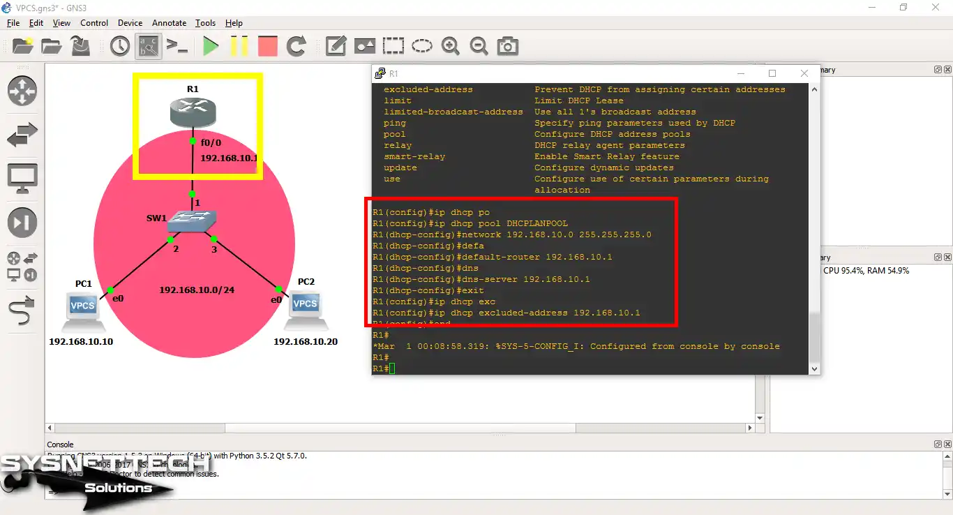
Step 7
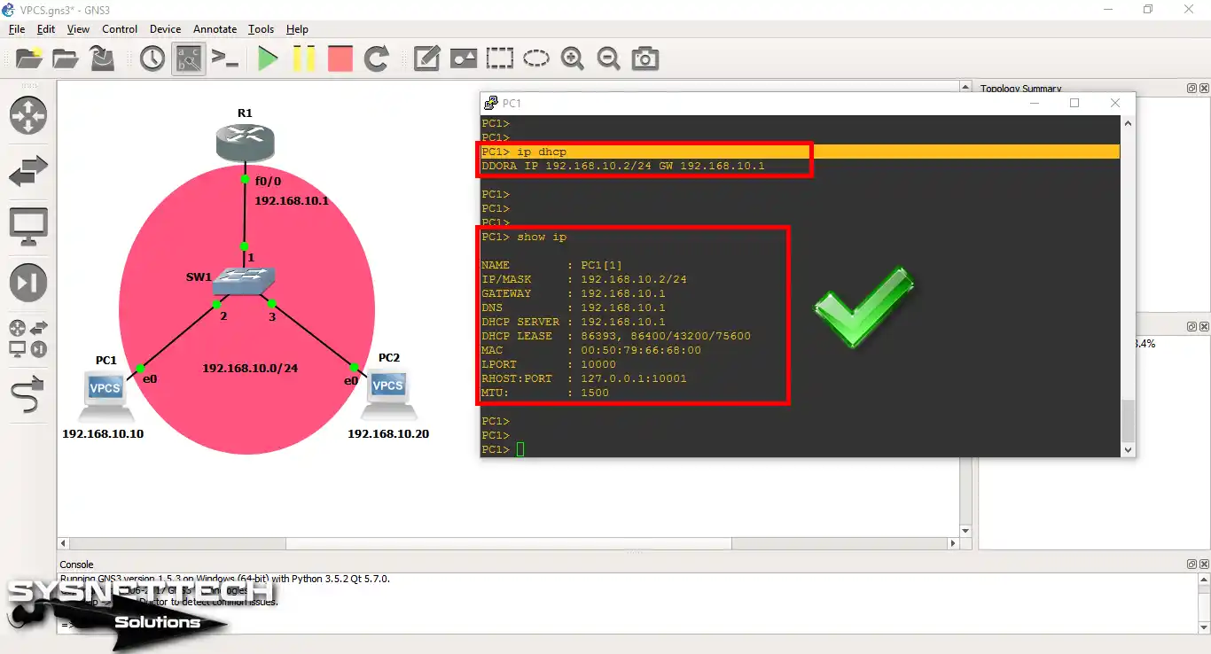
After configuring DHCP to assign automatic IP addresses to VPCS, execute ip dhcp on PC1.
The following image shows that VPCS PC1 receives its TCP/IP settings from the DHCP server you have configured on the Router.
Step 8
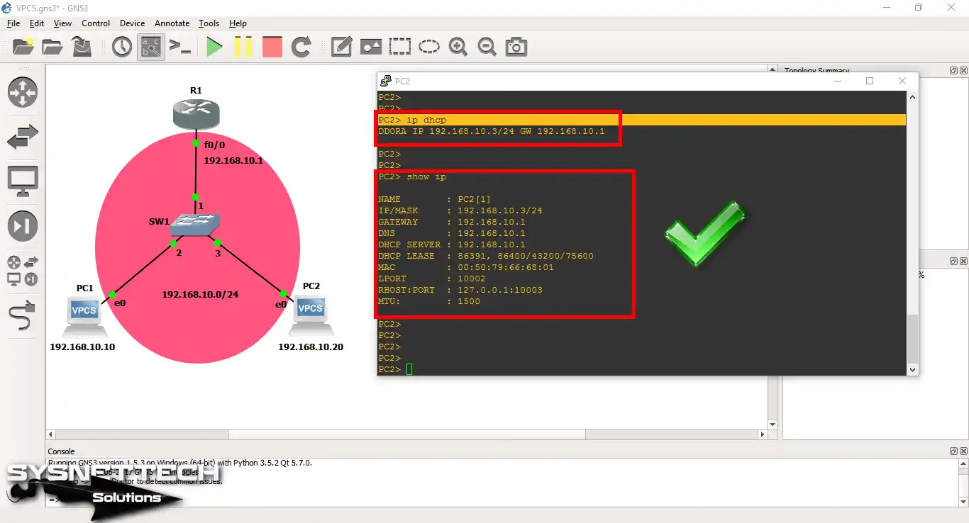
Likewise, execute ip dhcp to assign an automatic IP address to the VPCS PC2.
Step 9
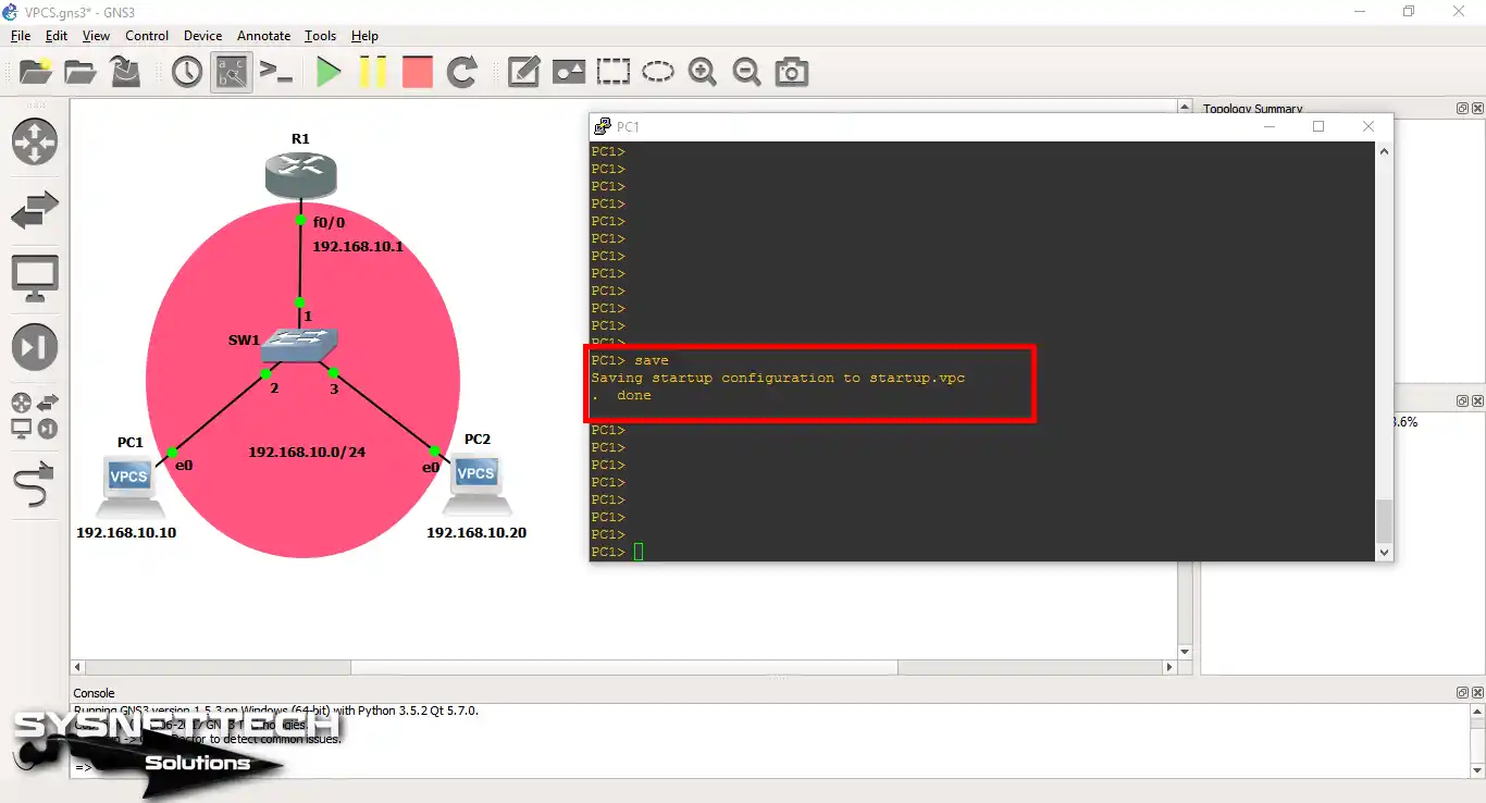
After reviewing the VPCS configuration steps, you can use the save command to save your settings.
Otherwise, the settings on the restarted or shut-down VPCS will be lost.
Configuration Commands
PC1> show ip
NAME : PC1[1]
IP/MASK : 0.0.0.0/0
GATEWAY : 0.0.0.0
DNS :
MAC : 00:50:79:66:68:00
LPORT : 10000
RHOST:PORT : 127.0.0.1:10001
MTU: : 1500
PC1> ip 192.168.10.10/24 192.168.10.1
Checking for duplicate address...
PC1 : 192.168.10.10 255.255.255.0 gateway 192.168.10.1
PC1> ip dhcp DDORA IP 192.168.10.2/24 GW 192.168.10.1 PC1> show ip NAME : PC1[1] IP/MASK : 192.168.10.2/24 GATEWAY : 192.168.10.1 DNS : 192.168.10.1 DHCP SERVER : 192.168.10.1 DHCP LEASE : 86393, 86400/43200/75600 MAC : 00:50:79:66:68:00 LPORT : 10000 RHOST:PORT : 127.0.0.1:10001 MTU: : 1500
PC1> save
Saving startup configuration to startup.vpc
. done
PC2> show ip
NAME : PC2[1]
IP/MASK : 0.0.0.0/0
GATEWAY : 0.0.0.0
DNS :
MAC : 00:50:79:66:68:01
LPORT : 10002
RHOST:PORT : 127.0.0.1:10003
MTU: : 1500
PC2> ip 192.168.10.20/24 192.168.10.1
Checking for duplicate address...
PC1 : 192.168.10.20 255.255.255.0 gateway 192.168.10.1
PC2> ip dhcp
DDORA IP 192.168.10.3/24 GW 192.168.10.1
PC2>
PC2>
PC2> show ip
NAME : PC2[1]
IP/MASK : 192.168.10.3/24
GATEWAY : 192.168.10.1
DNS : 192.168.10.1
DHCP SERVER : 192.168.10.1
DHCP LEASE : 86391, 86400/43200/75600
MAC : 00:50:79:66:68:01
LPORT : 10002
RHOST:PORT : 127.0.0.1:10003
MTU: : 1500
PC2> save
Saving startup configuration to startup.vpc
. done
R1#conf t
Enter configuration commands, one per line. End with CNTL/Z.
R1(config)#interface fastEthernet 0/0
R1(config-if)#ip address 192.168.10.1 255.255.255.0
R1(config-if)#no shutdown
R1(config-if)#exit
R1(config)#ip dhcp pool DHCPLANPOOL
R1(dhcp-config)#network 192.168.10.0 255.255.255.0
R1(dhcp-config)#default-router 192.168.10.1
R1(dhcp-config)#dns-server 192.168.10.1
R1(dhcp-config)#exit
R1(config)#ip dhcp excluded-address 192.168.10.1
R1(config)#end
R1#
How to Use Virtual PC Simulator ⇒ Video
To support us, you can watch the video below about VPCS connection with Switch and Router and subscribe to our YouTube channel!
Conclusion
In this article, we have examined how to set up VPCS settings to work more comfortably with Cisco exams with GNS3. Thanks for following us!

Great summary