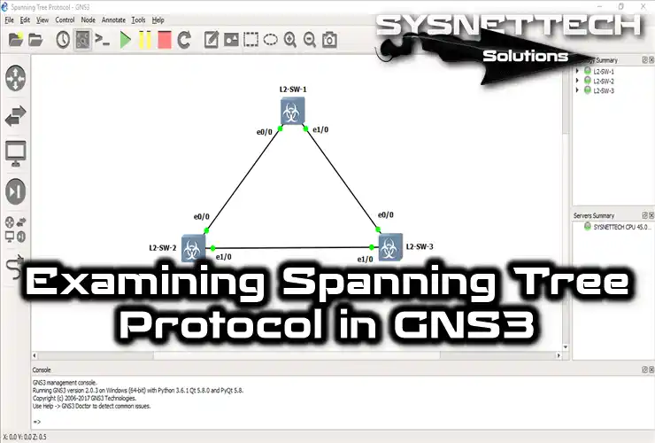
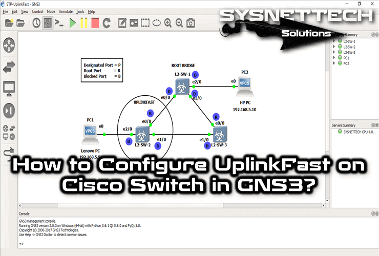
In computer networks, the Spanning Tree Protocol (STP) stops loops. In this article, we’ll look at how STP works on Layer 2 Switches with GNS3.
We’ll explore the selection of Designated, Root, and Blocked Ports. Plus, we’ll go over setting up STP and analyzing packets with Wireshark. If you want to know more about this protocol, keep reading!

Exploring How Spanning Tree Works Using GNS3
The Spanning Tree Protocol (STP) stops loops in OSI layer 2 networks. It does this by making a spanning tree topology. So this means there’s a path for data to go without loops.
The protocol makes sure there’s only one path active between devices. Plus, it picks a root bridge automatically. Basically, this stops extra links from being used.
Spanning Tree keeps the network stable, especially in extensive networks. It handles lots of paths between devices well. Plus, it stops congestion and broadcast storms. And it ensures there are no problems with network loops.
So, it stops network loops, making sure packets get where they need to go on time. That really boosts how well the whole network works.
Understanding How Does Spanning Tree Work
When setting up STP, we look at picking Designated, Root, and Blocked Ports. Because of that, it makes a logical tree shape to stop network loops.
The protocol picks a Root Bridge and then decides on Designated Ports. These ports send traffic to the Root Bridge. On the segment, Spanning Tree blocks other ports to stop traffic. In short, this algorithm works by switches exchanging BPDUs.
By looking at the info in the BPDUs, switches figure out what roles ports should have. Then, they decide which ports should do what jobs in the network topology.
How Does STP Protocol Select Its Root Port, Designated Port, or Blocked Ports?
Preventing loops is super essential for having a backup in the network. That’s where the STP comes in. So, it, which works on Layer 2, stops ports to avoid loops. This means there’s just one primary way for data to go.
Now, let’s use GNS3 to make and try out the STP port states.
Step 1
To start an STP project, first, open the GNS3 software. Then, create a new network project. After that, set up the components and settings you need for your design.

Step 2
Add three Layer 2 switches to your GNS3 workspace. These switches are essential for simulating networks. Moreover, they help you make a virtual setup for testing and fixing network problems.

Step 3
Once you’ve added three Layer 2 devices, start them all up and open the command prompts. In this setup, I’ve set all the Switches’ ports to GigabitEthernet. So, the GigabitEthernet Cost value for STP is 4.
To pick a Root Bridge, we’ll find the Switch with the smallest MAC address first. If we don’t choose the root device ourselves, it will figure it out automatically by looking at the MAC addresses.
To get the MAC address of the Cisco Switch SW1, go to its command line prompt. Then, type in the show spanning-tree command.

Step 4
As you can see in the image below, the MAC Address of SW1 is 00ff.9ee9.8a00. Let me give you additional information: you can understand the logic better if you work by adding notes to the work area. Now, let’s learn the SW2 and SW3 MAC addresses.

Step 5
Likewise, run the same command on the Switch SW2 command prompt. This time, you can see the MAC address of SW2.

Step 6
The MAC address of SW3 is 00ff.9e54.7700, as you can see in the image below. Now, let’s examine the priority values of all switches and compare them.

Step 7
The show spanning-tree shows Cisco Switch Priority values. By default, all switches have a Priority value of 32769.
As you can see, the Priority value of SW1 is 32769.

Step 8
Since we did not manually change the priority values, the value of SW2 remains at 32769. So, this indicates that it has the default Priority value.

Step 9
We’ve got the MAC addresses and Priority values of Cisco Switches. Since all Priority values are the same, the Switch with the smallest MAC address becomes the Root Bridge.
Therefore, SW2 is a Root Bridge. Now, let’s examine the ports selected by the Spanning Tree.
Run the show spanning-tree command on SW2. In the command output, you’ll notice that the Gig0/0 and Gig0/1 interfaces are Designated Ports. That’s because the interfaces of a Switch you pick as the Root Bridge will always be Designated. So, the Root device keeps sending BPDU packets to others regularly.

Step 10
As SW2 is the Root Bridge, SW1 and SW3 will choose their ports as Root Ports. This occurs because the Cost values of SW1 and SW3 interfaces are equal to those of SW2.
If we had made the connection between SW2 and SW3 with FastEthernet, things would have changed. This time, the SW3 GigabitEthernet 0/1 interface would be “Blocked.” This is because the FastEthernet Cost value is 19.
We can see the details in the show command output of SW1 and SW3. Examine the CLI and verify that the ports are Root Ports.

Step 11
One of the remaining interfaces will be “Blocked” because a loop will occur in the network environment. Since the primary purpose of the STP is to prevent loops, SW2’s GE 0/1 interface will be “Blocked.”
If we consider the interfaces between SW2 and SW3, we again consider the smallest MAC address. As a result, SW3’s ID is a Designated Port because it is smaller.

Step 12
You can analyze STP packets using Wireshark. Thus, right-click on the link or start capturing to see the packets sent between SW1 and SW2.

Step 13
Check the ethernet card in the Packet Capture window and click the OK button.

Step 14
When you open Wireshark, it starts analyzing packets right away. As shown in the picture below, the STP protocol works smoothly between Layer 2 Switches.

STP Show Commands
| Command | Explanation |
|---|---|
| 1) show spanning-tree summary | It shows summary information of the entire STP algorithm tree in the network. |
| 2) show spanning-tree detail | It shows detailed information for each VLAN as well as summary information. |
| 3) show spanning-tree root | It shows the information of the root bridge in the algorithm tree. |
| 4) show spanning-tree interface GigabitEthernet 0/0 | It shows STP tree information for a specific interface (in this example, GigabitEthernet 0/0). |
1) show spanning-tree summary

2) show spanning-tree detail

3) show spanning-tree root

4) show spanning-tree interface gigabitEthernet 0/0

Understanding How STP Works > Video
If you want to know more about how it works, we’ve got you covered. Watch our detailed video review below. Also, if you’re going to support us, please subscribe to our YouTube channel. Thanks a lot!
Frequently Asked Questions (FAQ) About STP Working Logic
- How does the STP election process work?
- How does a spanning tree protocol work?
- What is the mechanism of STP?
Conclusion
To sum up, STP is essential for stopping loops and keeping OSI layer 2 networks stable. By making a logical tree shape and choosing ports, this protocol stops loops and congestion. Also, it makes the network work better from loops. GNS3 helps you simulate and try out different STP setups, too.
Knowing how STP works is really important. Using it in network setups makes sure everything stays stable and efficient. In short, this helps build a strong network that lasts a long time.


