If you’re using network switches, it’s super important to know about STP (Spanning Tree protocol) and its port states. In simple terms, STP makes sure there are no loops in the network, keeping things stable even if something goes wrong. When a switch does its job, it uses essential parts called port states. In this article, we’ll look at the different port states and roles of STP & RSTP and how it takes care of the network setup.
When you turn on a switch, each of its ports (connections) goes through four steps. Blocking, Listening, Learning, and Forwarding are the port states. There’s also a fifth step, known as the Disabled state.
What are the States and Roles of Classic Spanning Tree?
Before we talk about port states, let’s quickly explain what STP does. In a network, a switch makes different paths for data to travel. This helps us grow our network by connecting more computers or devices. More importantly, it lets us make backup plans in extensive networks, like in companies.
However, having many paths comes with a cost. Usually, people at home don’t need this kind of setup. Still, it makes your network work better and last longer. But there’s also a problem – it might cause loops.
These loops we talked about make network packets go around and around forever. It’s like a sickness that uses up our resources. Also, it causes broadcast storms, making the network work less well.
Here’s where STP helps out. It makes sure only one path is active to stop these issues. It blocks the other paths, creating a logical tree-like structure. This way, it prevents both loops and broadcast problems.
What is the Port States Used by STP on a Switch?
We check or manage the ports or connections on the Switch using hardware LEDs. The colors of these LEDs show different conditions in the device. For instance, if it flashes orange first and then turns green. So, it means you’ve successfully linked a device to the network.
When the Switch starts up, it goes through different port states. Simply put, it takes about 50 seconds to finish these tasks. At the same time, the devices send frames called BPDU to each other. In this case, this helps stop any loops that might happen in the network.
In the network, switches figure out which one is the device using frames called BPDU. That is, at this stage, it decides which Switch will be the Root Bridge or which connection will be in Blocking mode. This way, there’s a backup plan between devices in the network. Thus, it helps you avoid loops with the STP protocol.
When you add a new switch to a network, the Spanning Tree Protocol takes its ports through 4 stages. In short, it does this to set up its connections without making a loop in a backup network.
The Port States of STP (Spanning Tree Protocol)
A switch in the network goes through four different port states until it discovers backup paths, that is, until it activates STP:
1. Blocking Port State
In a redundant network, the Switch starts in Blocking mode. Blocking mode blocks connection paths that will form a loop. Also, they do not send Data-Link Frames (Layer 2 Frames). It just listens to what’s on the network. It then receives and analyzes the BPDUs.
The blocking mode of the switch stops loops in the network when the STP convergence process happens. So, when the device starts up, the first 20 seconds are in Blocking mode. But you can check and adjust this time, which is called the “max-age timer,” on the device. Also, the Blocking Mode shows a solid orange color to let you know.
In short, when a switch is in blocking mode:
- It doesn’t send frames or learn MAC addresses.
- STP uses it to get everything in order.
- It shares info with other switches.
- It helps find the best way for data to go.
2. Listening Port State
After Blocking mode, which is for 20 seconds, the Switch goes to the Listening state. In this mode, it shows a notification with a blinking orange color. Afterward, it gets and sends BPDUs but doesn’t send frames. Also, it doesn’t start finding MAC addresses in Listening mode.
In Listening mode, it pays attention to the network with BPDUs. Then, if there’s a loop, it goes back to Blocking mode. But if there’s no loop, it moves on to the Learning state.
Next, it listens for BPDUs and gets the frames ready to send. Also, the Switch finishes Listening mode in 15 seconds.
Also, you can change this value with the “forward delay timer” command in the Cisco IOS software.
In short, when a switch is in the listening mode:
- After blocking, it goes into the Listening state.
- Now, it gets BPDU (Bridge Protocol Data Unit) messages.
- These messages tell it about the network setup and what’s going on with other switches.
- It’s still not sending any frames, but it’s getting ready to go to the next state.
3. Learning Port State
Right after the Switch finishes Listening mode, it goes into Learning mode. Then, it stays in this mode for 20 + 15 = 35 seconds. In this mode, the Switch can make a list of MAC addresses while it’s sending and getting BPDUs.
A port in Learning mode does not send data frames. The default value of this mode is 15 seconds, and you can change it with the “forward delay timer” command.
If a Switch is in Learning mode, you can see the blinking orange LED light from the panel on the hardware interface.
During the STP port states make the learning phase:
- After getting enough details from BPDU messages, the learning state is entered.
- Here, the interface figures out the MAC addresses of the devices connected to its connection.
- It adds these addresses to its MAC address list.
- But the interface still doesn’t send any frames.
4. Forwarding Port State
The final state of the Spanning Tree port is forwarding. After all the steps, it moves to this mode after 20 + 15 + 15 = 50 seconds. Then, in this mode, it handles BPDUs and finds out about MAC addresses.
Simply put, the Switch shows Forwarding mode with a blinking green light. So this signals that the device can now send and get data packets.
If the interface is a Designated or Root Port, it switches to Forwarding Mode.
So, to sum it up, the following things happen in Forwarding mode:
- After the learning state, the interface goes to the Forwarding state.
- Now, the Switch’s connection point is busy sending frames and taking part in moving data around the network.
- It carefully controls the transition from one state to another to stop network problems and loops.
- It makes sure the STP algorithm picks the best way for data to travel, avoiding loops and broadcast issues.
5. Disabled Port State – (Extra)
An interface on a Switch in the network may be “Disabled.” In fact, this status is the most basic connector expression.
Usually, the Disabled interface is “shutdown” by system administrators on purpose. So, this status doesn’t affect the network at all. Plus, it doesn’t send or get any data frames.
In easy words, Disabled mode means it’s turned off.
The Port Roles of STP (Spanning Tree Protocol)
We talked about switching ports. Now, let’s look at the various port roles you can have in STP.
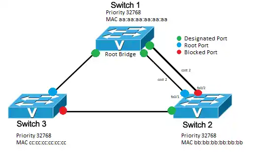
- Root Port (RP) Role
The root port is the switch connection that provides the quickest way to the root bridge. So, non-rooted Switches have one Root interface because they link to the closest device. So, this main output point sends frames to the bridge device.
- Designated Port (DP) Role
This role is on every LAN part to send frames to the root bridge. So, there’s just one DP on each LAN part. In simple terms, this is the port that’s the closest to the bridge device you picked. Also, every Switch that’s not the main one has at least one DP.
You set the port role of the Switches that send packets to the Root bridge device you have selected as DP.
- Blocking Port (BP) Role
This role includes Non-Root and Non-Designated. As its name says, it’s in blocking mode. So, it doesn’t send any data or frames. Its main job is to stop loops by not letting frames go through specific ports. In brief, when a switch’s Designated interface has a problem, the Blocking link steps in. This way, STP keeps the network running smoothly.o
What are the Port States and Roles of RSTP (Rapid Spanning Tree)?
RSTP is a better version of the original IEEE 802.1D Spanning Tree Protocol. People who manage PC systems or networks use it a lot in LANs with backup switches. Because of that, it’s faster than the old version.
They made RSTP to fix the slow speed problem of STP. In simple terms, classic STP has a convergence time of up to 50 seconds, while RSTP achieves this in 5-10 seconds.
RSTP Port States
RSTP uses three port states to work smoothly:
- Discarding
- Learning
- Forwarding
Now, let’s look at the RSTP port states we listed above.
- Discarding Port State
This is the first step of how RSTP works. If you set a switch’s port as Discarding, it won’t send any frames. So, when you first connect a device to this interface, it will be in Discarding mode. Plus, the interface will ignore any frames it gets.
But, if it gets a BPDU with the lowest path cost to the root bridge from other devices on the LAN, the Switch turns on this state.
- Learning Port State
In the next step, the port enters the Learning state. Here, it sends and gets frames from other devices in the network. Yet, it doesn’t make the MAC table in this mode. Specifically, it figures out the MAC of the data it’s getting.
If the Switch notices a higher BPDU value in things it gets, it turns on Learning mode.
- Forwarding Port State
After the learning state, the Switch can now send out packets. At this point, it gets frames, sends them out, and keeps the MAC table updated.
RSTP Port Roles
The different port roles in RSTP are:
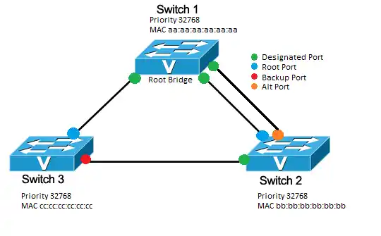
- Root Port Role
The root interface is the one closest to the root bridge switch. That is, it sends data from non-rooted devices to Root Bridge. In this role, this connection point is the path with the lowest cost.
- Designated Port Role
This role makes sure data goes to a particular LAN segment of the network. So, there’s only one Designated role for each part. Also, it picks the path with the lowest cost to the Switch as the DP.
- Alternate Port (AP) Role
These ports play a role as a backup. That is, they perform the Forwarding role in case a connector fails. Also, since they are redundant, they do not send frames. In short, Alternate Port provides redundancy.
- Backup Port Role
Suppose something goes wrong with the root connector; the Backup role steps in. Also, this role makes sure there’s a path to the root bridge device without any loops.
- Disabled Port Role
The name of this role in RSTP tells us what it’s for. Simply put, an interface you set up with this role won’t be part of the Spanning Tree.
Tips to Make STP and RSTP Work Better
It’s crucial to know about port states and roles to make your network work better and stay healthy. So, here are some essential tips to improve the Spanning Tree algorithm:
- Put the Root bridge device in the center to make the Convergence time as short as possible.
- When picking the Designated, figure out the cost of each socket on the Switch.
- Use the “priority” command to choose the root bridge.
- Turn on portfast for machines used by end-users.
- Lastly, the sockets for devices that don’t use STP as an edge port should be set up.
Comparing The Port States & Roles of STP and RSTP
Frequently Asked Questions (FAQ) for Port States and Roles
- What do Spanning Tree Port states and roles do?
- How does the Switch transition between port states?
- What makes ports switch between states?
- Can the port go straight from Blocking to Forwarding?
Conclusion
When you add a new Switch to a backup network, it starts in Blocking mode. If there are many devices in the topology, your device can’t go straight to Forwarding. Doing that might create loops in the network. So, to prevent issues, your Switch goes through a process of listening and learning, and then it starts sending data on the network.
When you’re connecting a PC or server to a switch socket, use PortFast. This way, end-users or important company machines can start using your LAN right away. So, it goes straight to Forwarding mode. Thanks for sticking with us!

TolgaBagci
Hi, I'm Tolga, a computer expert with 20 years of experience. I help fix computer issues with things like hardware, systems, networks, virtualization, servers, and operating systems. Check out my website for helpful info, and feel free to ask me anything. Keep yourself in the loop about the newest technologies!